FORMS / WORKFLOWS
Start with
the problem.
A drawing change. A first prototype. A pump that needs a different operating point. See how the work breaks down—and where Forms fits.
These guides describe the intended workflow across Forms. Product status and current previews are shown for each one.
01 / DRAWING CHANGES
Close the loop on drawing changes.
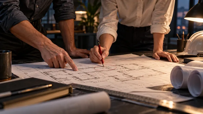
Comments arrive as screenshots, emails, and marks on different copies of a drawing. The designer has to reconstruct what changed before making the change itself.
Put the intent, the drawing, and the review into deliberate steps. Keep a clear issue to resolve at each handoff.
- 01Forms Sketch
Explain the change.
Sketch over an image or PDF page. Use arrows, callouts, and text to show the location and the reason for a change.
In development
- 02Forms 2D
Resolve it in the drawing.
Work through the geometry, annotation, layers, and sheets in a drafting environment. Check the affected notes and dimensions along with the linework.
Launches
- 03Forms Review
Review the result.
Use drawing-set review and redlines to communicate what remains to be resolved. Review’s focus is the document conversation around the engineering.
Launches

THE WORK TO CARRY FORWARD
A clear change request, a revised drawing, and a review that explains the remaining decisions.
WHERE TO START
Try the drawing and annotation stages in the current 2D and Sketch browser previews. Review is scheduled for December 1, 2026.
Try the 2D preview ↗02 / PARTS & PROTOTYPES
Take a part toward a physical prototype.
A part can look finished and still be difficult to manufacture. Dimensions, assembly relationships, wall thickness, and printer constraints need attention before a first prototype.
Treat authoring, fit, and fabrication as separate decisions, with a chance to inspect the work between them.
- 01Forms Element
Define the part.
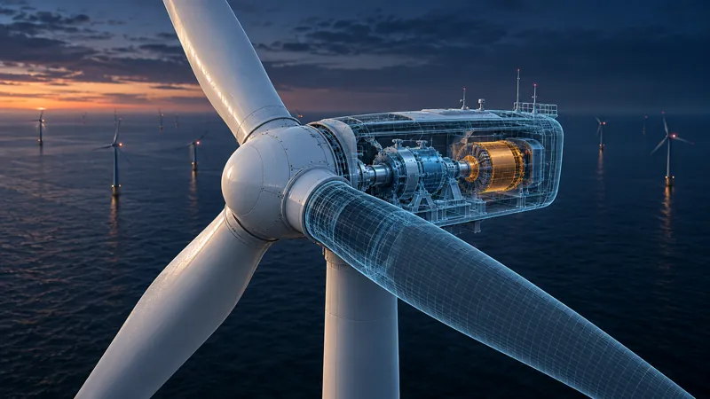
Element’s product direction centers on feature history, parameters, parts, and assembly relationships. Establish the dimensions and relationships that matter.
Launches
- 02Forms Make
Prepare the prototype.
Make supports native Element handoffs and supported solid-source exchange. Arrange parts and plates, check fit and walls, and export STL or neutral 3MF when another slicer is needed.
In development
- 03Forms Make
Inspect the print plan.
In Windows Make, choose the printer, material, and process; inspect the generated toolpaths before exporting G-code. Browser Make can save a job for the desktop application.
In development

THE WORK TO CARRY FORWARD
An inspectable part and a deliberate print plan. Physical fit and print quality still need validation on the actual prototype.
WHERE TO START
Make’s browser and Windows previews are available. Element is scheduled for February 1, 2027.
Open Make ↗03 / PUMPING SYSTEMS
Work through a pumping-system change.
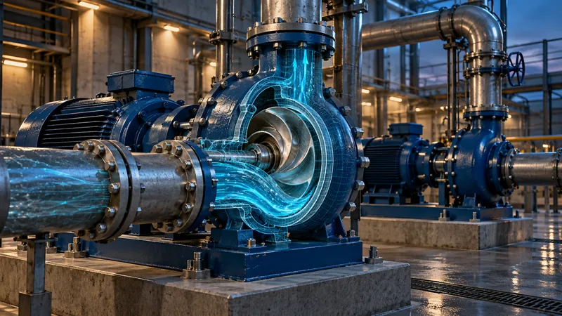
Changing a pump affects more than its symbol. Pipe conditions, operating points, instrument locations, and control behavior all need to describe the same system.
Work through the process, the hydraulic model, and the control intent together. Record the assumptions that need to be checked across the disciplines.
- 01Forms Process
Describe the system.
Process is being developed around equipment, piping, instruments, and P&ID intent. Establish the equipment and connections before detailing the change.
In development
- 02Forms Fluid
Examine the operating conditions.
Fluid’s development workspace brings pumping-system models and hydraulic results into view. Inspect the assumptions, flow conditions, and continuity checks behind a proposed arrangement.
Launches
- 03Forms Logic
Define the control response.
Logic’s development work structures equipment, signals, and control narratives. State what the system should do, which inputs drive decisions, and which outputs carry them out.
In development
THE WORK TO CARRY FORWARD
A coordinated set of process, hydraulic, and control decisions to review before implementation.
WHERE TO START
Fluid is scheduled for January 1, 2027. Process and Logic are in development; their product pages show the current direction and available evidence.
See Fluid development ↗04 / SITE DRAWINGS
Turn site constraints into a drawing package.
Terrain and alignment decisions have consequences beyond the plan view. A change needs to make sense in the profile, the corridor, and the sheet used to communicate it.
Make each representation answer a specific question, then review them together before passing the work on.

- 01Forms Civil
Work from the ground.
Civil’s direction includes terrain surfaces, alignments, profiles, and corridors. Start with the site conditions that constrain the route.
In development
- 02Forms 2D
Make the intent legible.
Develop the drawing with layers, dimensions, symbols, and sheets. Explain the conditions and details that a model view alone cannot communicate.
Launches
- 03Forms Review
Check the package.
Use document review to ask whether the plans, profiles, notes, and details tell a consistent story. Keep the questions tied to a specific drawing location.
Launches
THE WORK TO CARRY FORWARD
A drawing package that communicates the design decisions and the site conditions behind them.
WHERE TO START
The 2D preview is available. 2D and Review are scheduled for December 1, 2026; Civil is in development.
See Civil development ↗05 / DESIGN DECISIONS
Make a design easier to understand.
The person reviewing a design may not read the same drawings as the person authoring it. A technically detailed model can still leave the important decision unclear.
Choose the question first. Then choose the geometry, viewpoint, and visual context that help answer it.

- 01Forms 3D
Establish the spatial idea.
Forms 3D is being developed around geometry, views, transformations, and engineering context. Use a spatial view to make relationships easier to inspect.
Launches
- 02Forms Vision
Choose what the view communicates.
Vision’s direction covers materials, lighting, cameras, and presentation. Focus the view on the arrangement, appearance, or context that needs a decision.
In development
- 03Forms Review
Capture the response.
Bring the discussion back to specific questions and review notes. A compelling image should lead to a decision that can be described and acted on.
Launches
THE WORK TO CARRY FORWARD
A focused visual explanation and a clear record of what the reviewer needs to decide.
WHERE TO START
3D is scheduled for January 1, 2027. Vision is in development. Current product pages include genuine development captures.
See 3D development ↗06 / CIRCUIT EXPERIMENTS
Find out what an electronics idea does.
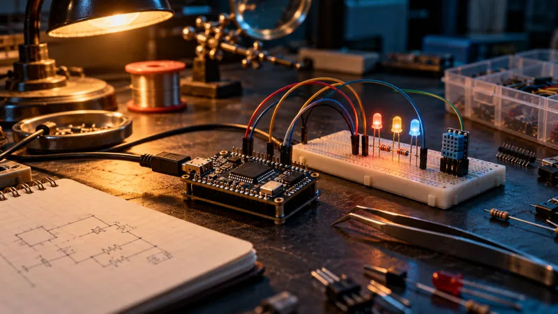
An electronics idea often starts as a drawing and a guess. Wiring, firmware, and analog behavior need different kinds of checks before involving physical hardware.
Make the idea visible, build a simulated project, and choose the analysis that matches the question.
- 01Forms Sketch
Map the idea.
Draw the blocks, inputs, outputs, and connections. Add notes and callouts before committing to component-level wiring.
In development
- 02Forms Tinker
Build and run a project.
Choose catalog parts, connect pins, and try a starter. Tinker identifies supported simulation engines and the boundaries of each part and firmware path.
In development
- 03Forms Tinker
Inspect the behavior.
Use the separate local ngspice tools for supported analog analyses. Keep simulation separate from physical serial actions, and save a portable project when the experiment is useful.
In development
THE WORK TO CARRY FORWARD
A saved experiment with inspectable circuit connections, source, and supported analysis results.
WHERE TO START
Sketch and Tinker browser previews are available. Tinker’s Windows preview is also available; both products remain in development.
Open Tinker ↗